SMT Pick and Place: How the Process Works
Surface-mount technology (SMT) is a widely used method for assembling electronic circuit boards. A key step in SMT production is pick and place: the process of positioning surface-mount components onto a printed circuit board (PCB) before soldering. Pick-and-place machines automate this work, helping manufacturers assemble boards quickly and consistently.
What Is SMT Pick and Place?
SMT pick and place is the automated placement of electronic components onto designated locations on a PCB. Components may include resistors, capacitors, integrated circuits, connectors, and other parts designed to mount directly on the board’s surface.
Before placement, solder paste is typically applied to the PCB’s pads through a stencil. The pick-and-place machine then uses a component feeder and a placement head to collect each part and position it on the paste-covered pads. After placement, the board usually passes through a reflow oven, where heat melts the solder paste and forms electrical and mechanical connections.
How a Pick-and-Place Machine Works
Although machine designs vary, most SMT pick-and-place systems follow a similar sequence:
- Board loading: A PCB enters the machine and is held in position for assembly.
- Program and data setup: Placement instructions identify each component, its location, and its orientation. These instructions are commonly created from PCB design and manufacturing data.
- Component feeding: Components are supplied from reels, trays, tubes, or other feeders.
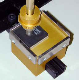
- Component pickup: A nozzle, vacuum tool, or other pickup mechanism collects a component from its feeder.
- Vision inspection: Cameras may check the component’s position and orientation so the machine can correct alignment before placement.
- Placement: The machine positions the component on the corresponding pads of the PCB.
- Inspection and soldering: The assembled board may be inspected before entering a reflow oven for soldering.
Key Parts of an SMT Pick-and-Place System
- Placement head: Moves components from the feeders to the PCB.
- Nozzles: Pick up components of different sizes and shapes. The appropriate nozzle depends on the component and machine.
- Feeders: Present components to the placement head in a controlled sequence.
- Vision system: Helps identify component orientation and improve placement alignment.
- Board transport and support: Moves and secures the PCB during assembly.
- Control software: Uses placement data to coordinate machine movements and production settings.
Why Pick-and-Place Automation Matters
Manual placement can be suitable for prototypes or very small production runs, but it becomes difficult to maintain speed and consistency as board complexity and volume increase. Automated pick-and-place equipment can offer several advantages:
- Higher throughput: Machines can place many components in a short period, depending on the equipment, board design, and production setup.
- Repeatable placement: Automation helps maintain consistent positioning across production runs.
- Support for small components: Modern systems can handle a range of component sizes, including very small surface-mount parts.
- Reduced handling: Automated assembly limits the need to handle components individually.
- Scalable production: Pick-and-place equipment can support applications ranging from prototype assembly to high-volume manufacturing.
Factors That Affect Placement Quality
Accurate placement depends on more than the machine itself. Several parts of the production process need to work together:
- PCB design and data: Correct component coordinates, footprints, and rotation values are essential.
- Solder-paste printing: Poorly printed paste can contribute to misalignment, weak joints, or solder defects.
- Component condition: Parts should be stored and handled according to their requirements, especially when they are sensitive to moisture or electrostatic discharge.
- Feeder setup: Incorrectly loaded or poorly maintained feeders can cause pickup errors.
- Nozzle selection and condition: A suitable, clean nozzle supports reliable component pickup.
- Machine calibration: Regular checks help keep placement performance within the required tolerances.
- Inspection: In-process checks can help identify placement problems before they affect larger production runs.
Choosing a Pick-and-Place Machine
The right system depends on the products being assembled and the production environment. Important considerations include expected production volume, the range of component sizes, board dimensions, placement accuracy requirements, feeder capacity, software compatibility, and available technical support.
It is also useful to consider the full assembly line rather than evaluating the placement machine in isolation. The equipment should work effectively with solder-paste printing, board handling, inspection, and reflow processes. For prototype work, flexibility and easy setup may be priorities. For higher-volume production, throughput, uptime, and changeover efficiency may be more important.
Keeping the Process Reliable
Routine maintenance and careful setup help reduce placement errors and unplanned downtime. Production teams commonly follow equipment guidelines for cleaning nozzles, inspecting feeders, verifying calibration, and checking machine vision. Keeping component libraries and placement programs current can also help prevent setup mistakes when products change.
When a placement defect occurs, it is important to investigate the entire process. The cause may involve the placement program, component packaging, feeder operation, solder-paste printing, or PCB design—not just the pick-and-place machine.
Conclusion
SMT pick and place is an essential stage in modern electronics manufacturing. By positioning components accurately and consistently, pick-and-place systems help prepare PCBs for reliable soldering and further testing. A well-managed process combines appropriate equipment with accurate production data, sound material handling, regular maintenance, and effective inspection.
7 Essential Tips for Optimizing SMT Pick and Place Operations
- Verify component polarity and orientation before placement.
- Keep feeders loaded and calibrated correctly.
- Use the right nozzle for each component size.
- Check pick-and-place coordinates against the PCB design.
- Set placement force to avoid damaging components.
- Inspect solder paste before running the board.
- Run a first-article inspection before full production.
Verify component polarity and orientation before placement.
Before starting an SMT pick-and-place run, verify the polarity and orientation of every component that has a defined direction. Diodes, electrolytic capacitors, LEDs, and many integrated circuits can malfunction or be damaged if installed incorrectly. Check the PCB silkscreen, assembly drawings, component markings, and placement-program data, then confirm that feeders are loaded in the correct direction. Catching orientation errors before placement can prevent costly rework, reduce wasted components, and improve assembly reliability.
Keep feeders loaded and calibrated correctly.
Keep feeders loaded and calibrated correctly to help ensure components are picked up and placed accurately. Confirm that each feeder contains the right component, is seated securely, and is configured for the correct package and feed settings. Regular calibration and inspection can reduce mispicks, placement errors, production interruptions, and component waste.
Use the right nozzle for each component size.
Use the right nozzle for each component size to help ensure reliable pickup and accurate placement. A nozzle that is too small may not hold the part securely, while one that is too large can interfere with nearby components or damage the part. Match the nozzle to the component’s shape and dimensions, and keep it clean and in good condition to reduce pickup errors and improve SMT assembly quality.
Check pick-and-place coordinates against the PCB design.
Before starting production, verify the pick-and-place coordinates against the PCB design files to make sure every component is assigned to the correct location and orientation. Pay special attention to rotation values, board origin, and any differences between the top and bottom layers. Catching coordinate mismatches early can prevent misplaced components, assembly delays, and costly rework.
Set placement force to avoid damaging components.
Set the placement force carefully to ensure components are seated securely without being damaged. Too much force can crack fragile parts, deform leads, or push solder paste out of position, while too little may leave components poorly seated. Follow the machine and component manufacturer’s recommendations, and verify the setting with test placements and inspection—especially when changing component types or board designs.
Inspect solder paste before running the board.
Inspecting solder paste before running a board through SMT pick and place can help prevent placement and soldering defects. Check that the paste is applied evenly, covers the intended pads, and has no smears, gaps, or bridges between adjacent pads. If the deposit looks incorrect, pause and correct the issue before loading the board, since components may shift or form poor solder joints when the paste is inconsistent.
Run a first-article inspection before full production.
Run a first-article inspection before starting full production to confirm that the SMT pick-and-place setup is working as intended. Check the initial assembled board for component placement, orientation, polarity, and solder-paste alignment, and compare it with the design files and assembly requirements. Catching setup or programming errors early can prevent defects from affecting an entire production run, saving time, materials, and rework.
No Responses